
During the summer of 2023, I had the opportunity to work at a specialized CNC machining firm, where we produced gas handling solutions for the natural gas industry, with rated pressures ranging from 400, to 2000 bar in the new hydrogen products. Amongst their toy shop were a number of high end Okuma and DMG Mori (and more!) CNC mills and lathes, running semi-autonomously with robotic stock and part loaders.

2026 Update
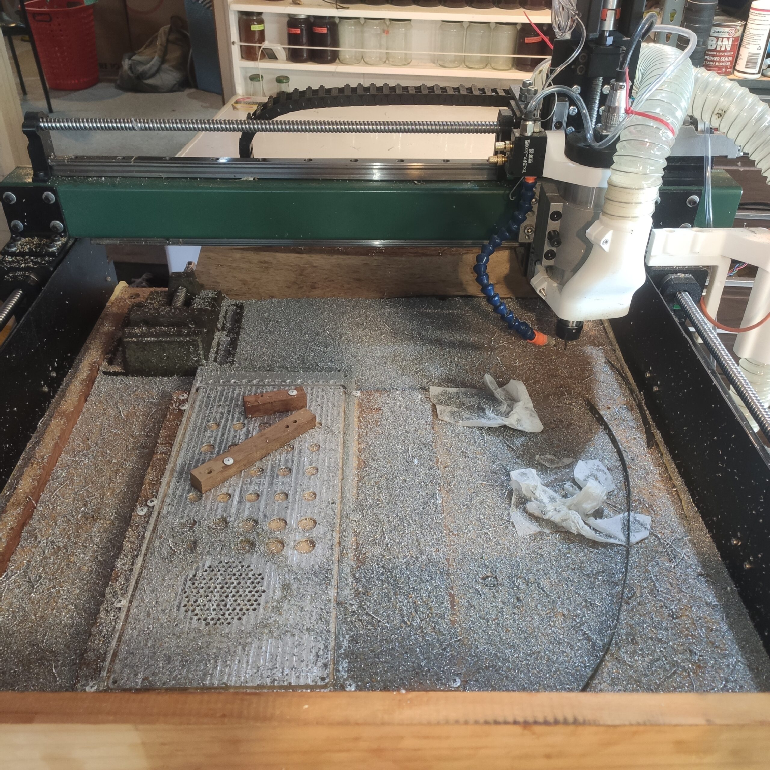
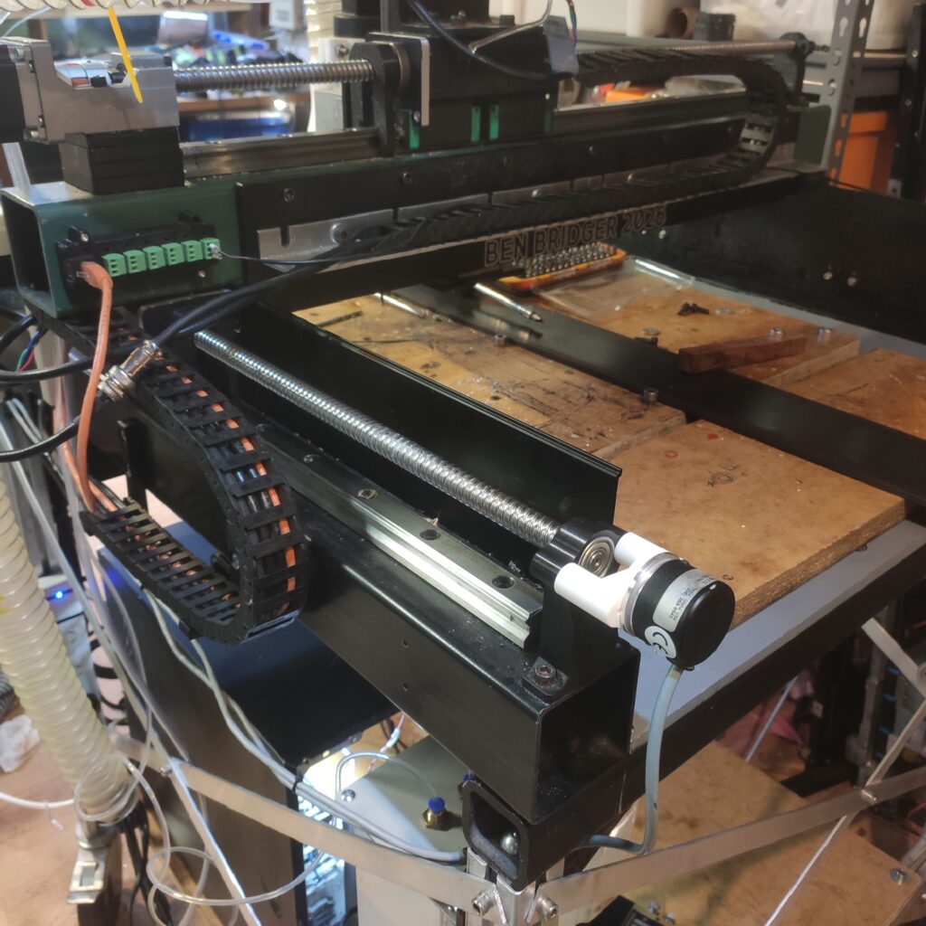
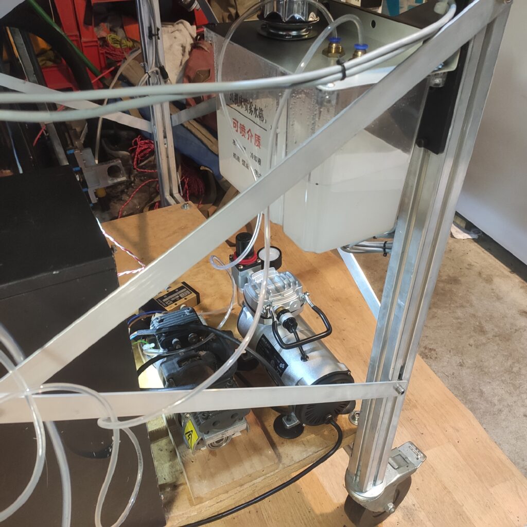
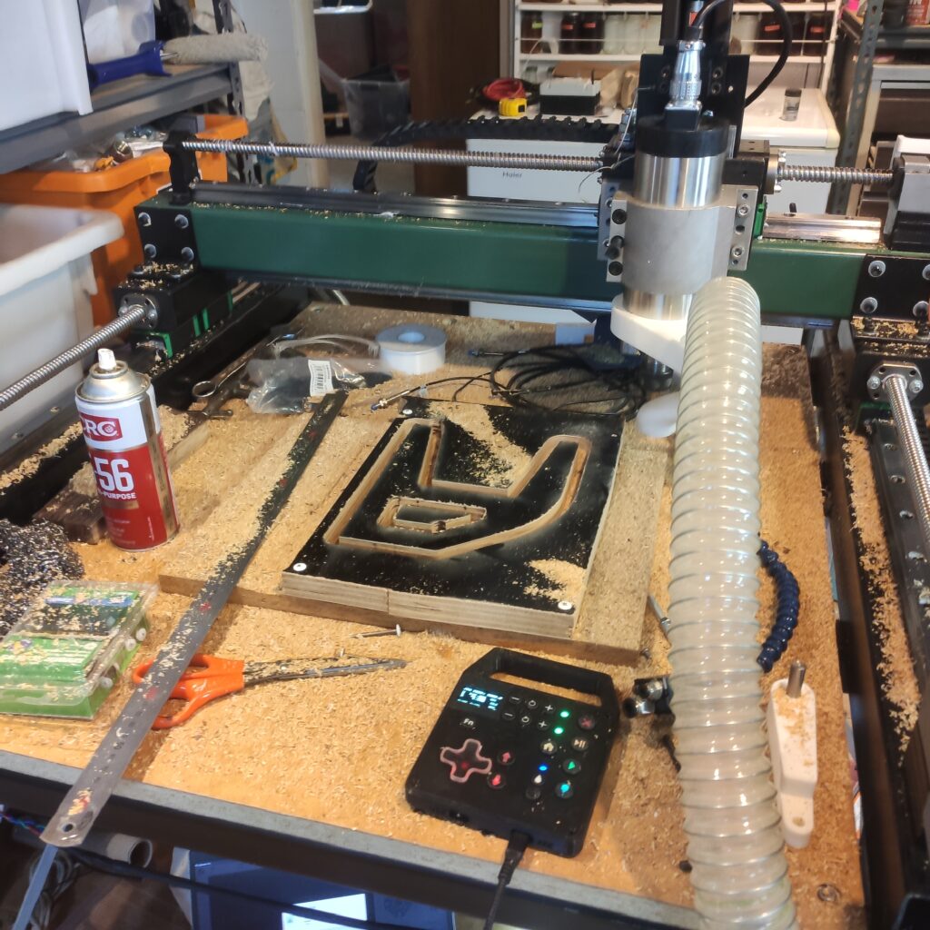
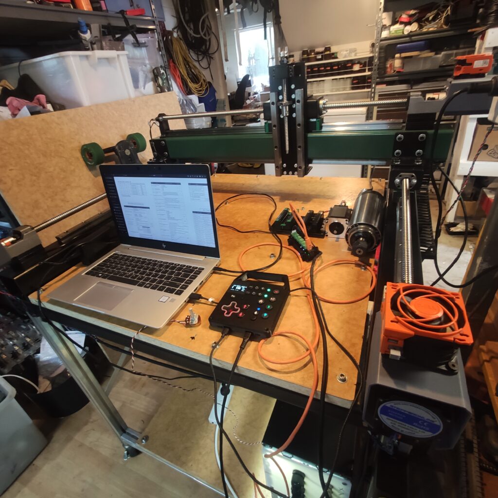
A lot of changes have happened to the machine since the original design. The wooden bench has been replaced by one made from 4040 extrusion bolted onto the underside of the machine base. Mist cooling is provided by a small air compressor and coolant tank located under the machine. A mixture of IPA, water, and oil is used as coolant, with a bubbler in the tank to keep the oil in suspension. Alternatively a pure oil mist seems to work well, which is dispensed from a small bottle mounted behind the z-axis.
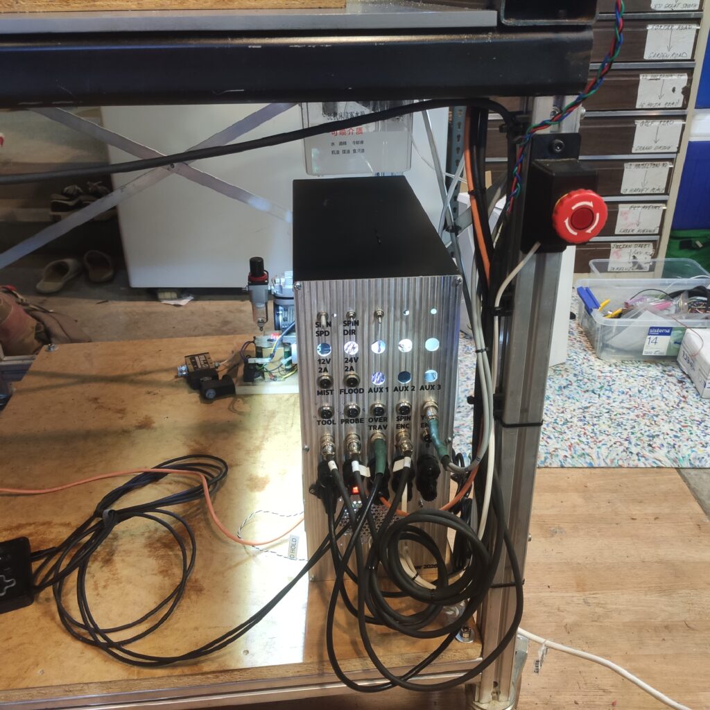
The spindle is set up to take an analog speed input from either the controller, or the panel mounted potentiometer, set using one of the toggle switches. The other toggle switch is a 2-pole, 2-throw, with three positions to set direction to forwards, reverse, or forward-enabled by the controller.
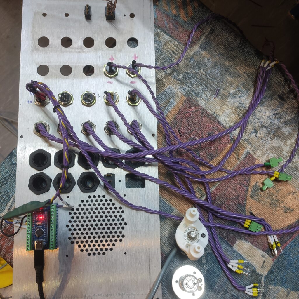
The machine has been equipped with encoders on the ganged y-axis, with position outputs being compared by an Arduino Nano microcontroller, which sends a pause command to the controller if it detects a significant difference between them. The microcontroller also reads spindle speed via a hall effect sensor and magnet placed on the rear of the spindle, pausing the machine if it detects a stall.
A 10mm plate has been bolted to the gantry to add bending and torsional stiffness. Even without this stiffener, parts have been cut from mild steel at 160mm3/s or 9600mm3/min (4-flute 4mm carbide endmill, 2mm stepdown, 12k RPM, 1200mm/min), with no chatter visible and the spindle not slowing down! For reference this is about 8x the material deposition rate of common Bambu Lab 3D Printers.
Machining Gallery

Background
The original plan was to build an OpenBuilds MiniMill. This budget turret-style router uses a full aluminium frame, with v-wheels instead of linear rails in order to save cost. My initial plan was to replace this frame with one cast from fiber concrete, with the extrusions for the v-wheels cast in place, improving the stiffness and damping capability of the original design. After some time however, the limitations of this design became clear, particularly due to its small work area and the intrinsically poor stiffness of the v-wheels. It was then decided that working from a more capable design would yield a far more useful machine in the long run.


The question was then what style and design to choose. A turret mill would provide the highest stiffness, though at the expense of a smaller work area compared to a gantry-style – and I wanted the option of routing large sheets for cabinetry, meaning the workpiece wanted to be stationary. There were also practical considerations which went against a turret mill – would performance be bottlenecked by construction quality (lack of access to a mill to produce machine components), and stiffness underutilized with a high-speed spindle.
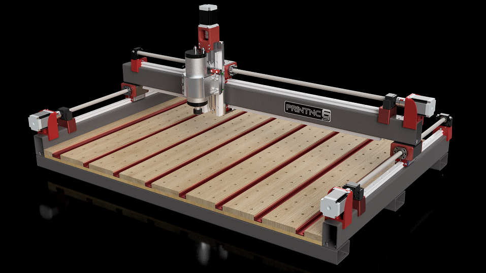
The eventual decision was made to loosely base the design on the PrintNC, a parametric router design that uses off the shelf steel RHS sections to mount Hiwin-style HGR20 linear rails. Compared to many of the designs utilizing aluminium extrusion, the choice of steel provides greater stiffness, damping, and can be obtained for a substantially lower cost in Auckland.
The base design PrintNC uses a single HGW20-CC carriage on each 20mm rail – two on each of the x, y, and z axes. These linear carriages are shockingly strong for their size, each rated for a 27.1kN dynamic load, and 200Nm pitch moment (see the red outline in the below image for the similar HGH20-CA). RHS ‘Rollers’ are bolted to each carriage, through which the SFU1610 ballscrews pass, and to which the gantry and z-plate are fastened.
The PrintNC is designed to be built without the need for a CNC mill, making great use of 3D Printed drilling guides, and temporary structural components, which have just enough strength to allow the machine to mill its own replacement aluminium parts.


My Design – Adapted from the PrintNC


The original PrintNC was designed with primarily wood routing, and milling of aluminium, with a working area of 960mm x 600mm. A number of departures from this design were influenced largely by my desired capabilities, space constraints, and cost.
A larger work area would be desirable for routing larger timber and plywood, but at the expense of additional space required (in short supply), and reduced stiffness, making the machine less suitable for milling. On the other hand, a significant portion of the BOM cost was also fixed regardless of size, such as the electronics, wiring, tooling, etc.
In the end, after a dive into the rough costs of the linear motion components (see below), a work area of 600x550mm was decided upon, to balance cost and space against utility and stiffness – 600mm in X allows half-sheets of plywood (1200x2400mm) to be run through the machine.
As it turned out, I later found a local supplier of imported linear rails and carriages at delightfully low prices . This changed up the cost calculus, and lead to the second major design departure: Moving from HGR20 to HGR25 (20 to 25mm) linear rails, and doubling up the carriages on the Y-axis, and X-axis top rail.
This came with a substantial increase in stiffness and rated load, with the dynamic load and pitch moment of each carriage increasing from 27.1-34.9kN (+29%), and 0.20-0.33kNm (+65%) respectively, and the rail mass increasing from 2.21-3.21kg/m (+45%). While the former two ratings are well in excess of what my machine would ever experience, more important is the increase in mounting hole size on the HGH25-CA carriages from M5 to M6, and rail stiffness, important considering the hollow box sections the rails are bolted to.
The new larger rails and carriages forced the redesign of a number of components, including the ballscrew mounts, X and Y rollers, and Z-axis lower mounting bracket, which lead to the decision to completely remodel the assembly from scratch in Autodesk Inventor.
Testing the Waters – rough linear motion costs


Some extra cost comparisons (Current March 2025)- ballscrew alternate suppliers, leadscrews, and for fun an alternative ‘block and tackle’ style arrangement using 2GT timing belt.


Frame Multi-Body CAD Model
The frame for the CNC was built up using a parametric multi-body approach, with critical dimensions driven by an excel sheet. The sheet contains a total of 107 parameters, though admittedly the model usually requires some fixing after a significant parameter change.
The model was designed to minimize reliance on solid geometry where possible to improve its robustness, with many critical reference frames laid out as work planes at the start of the part, positioned parametrically.
This approach was something new for me, and to some extent was an exercise in pushing myself to the extreme degree in multi-body modelling. The resultant model tree for the part is extremely long, and often presents difficulties when attempting to locate particular features. In hindsight, the drill guides (visible in red) should have used a derived copy of the required frame bodies, rather than cluttering up the model tree. Later drill guides used this approach.
The same applies to the two adaptive cable chains, which could have just as easily been modeled separately using derived geometry and parameters from the spreadsheet.


Machine Frame
The frame uses three main steel sections:
- 4x 900mm 50x50x6mm SHS for the base.
- 1x 950mm 75x75x4mm SHS for the X-axis member (gantry).
- 2x 900mm 75x75x3mm SHS for the Y-axis members.
The gantry member is significantly upgraded from the original PrintNC design (75x50x4mm), providing approximately 3 and 2x the bending and torsional stiffness respectively.
The four base members were reused from old garage posts to save cost, hence the excessive wall thickness and rough appearance, though dimensionally they are fine when compared against a straight-edge. Because of the space constraints inside the 50x50x6mm SHS (75x50x4mm RHS on PrintNC), the fastening solution for each connection was changed from 4x M6 to 2x M10 bolts. This arrangement isn’t ideal to resist racking of the frame, however that function is intended to be provided by the steel fixture plate, similar to the role of GIB board in residential construction.
3mm SHS was used for the Y-axis members as it was significantly cheaper than 4mm. This turned out to be a poor decision however, as later cantilever-beam calculations revealed that deflection against the tool load was not insignificant (170µm/kN @3mm vs 72µm/kN @4mm. The thread strength was also somewhat lacking for a 3mm wall section, with one rail hole being accidently stripped by over torquing.

3D Printed drilling guides were used to mark out pilot holes, which were then drilled and tapped as required. The rails themselves were used to align their mounting holes, with the rail first being aligned centered and parallel down the SHS with calipers, and clamped in place to allow each hole to be center-punched.
Once the frame was assembled, squaring was accomplished by measuring the two diagonals across the frame between Y-rail holes, and adjusting the frame until they were equal. During this process the gantry could be slid along the rails, forcing them to remain parallel. The gantry itself also had to be brought square, which was done with the rear of the machine as the reference plane.
To finally align each rail, a dial indicator was attached to each roller, and the rail mounting bolts adjusted until the the rail was parallel with each respective member.
Fixture Plate
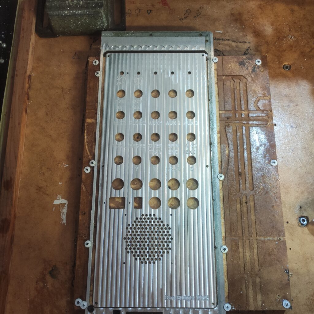
In step with the frame’s rigidity upgrade, a proper drilled and tapped (M8 spaced 100mm C2C) has been included as an upgrade over the router-style MDF board of the original PrintNC, which doesn’t allow the use of coolant when cutting aluminium/steel. This was drilled on the machine by sliding the plate in the y-axis to extend the machine’s effective travel.
The design is parametric to allow different flat bar sections to be used for the fixture plate – The CAD model has 200x6mm flat bar, but that may be changed to 100×6 so that I can buy a full 6m length ($16/m vs $22.5/m). The original plan was also to cast fiber concrete into the machine base under the fixture plate, with cast-in-place anchors from the fixture plate and frame members (hence the overhanging fixture plate edge in the CAD). This would give the machine a huge amount of racking strength and increase vibration deadening, though at the expense of preventing any future disassembly or realignment.


Ballscrew Mounts
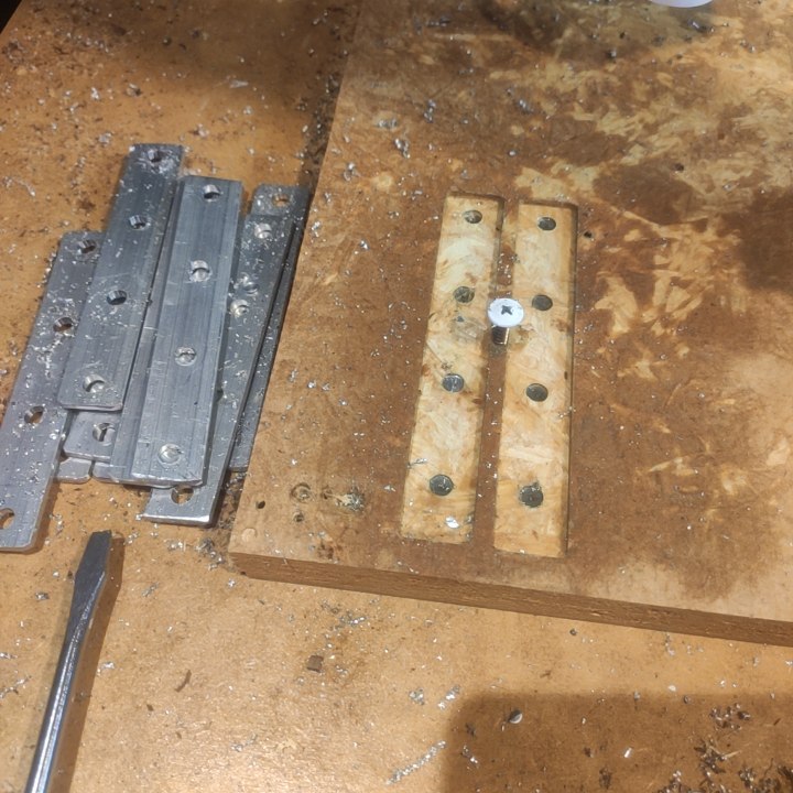
The ballscrew mounts were something of a mission to design, taking several iterations before a final design was settled on. The initial plan was to use the same BK12 bearing blocks used on the original PrintNC, for which a few mounting options were conceptualized. It was eventually decided however that this was not a good solution, due to the lack of an integrated motor mount, and a relatively small contact area. The HM12-57-C5 (12mm bore, NEMA23 motor mount, angular contact bearings for thrust capacity) was chosen as an alternative, with the mount design settling on a stack of four 60x10mm steel flat bar. The measured accuracy on these were surprisingly good, with each plate averaging just 175µm undersize from the rolling mill.


The twelve HM12 mount sections were cut with an angle grinder to their 65mm lengths from a length of 60x10mm flat bar.


Designing and Building a Workbench
A fairly simple timber workbench was originally designed and built to support the CNC machine, with dimensions of 1m deep by 1.2m wide by 0.9m high. Two shelves are provided, and the frame is enclosed on three sides to keep dust out, and contribute racking strength. The bench was designed as a multi-body part, driven by fourteen parameters in an excel sheet. The framing is comprised of 90x45mm untreated timber (only $4/m Inc. GST), fastened with 14G-75mm wood screws, with 8G-40mm screws to secure the panels.
A total of ~12.5m of 45x90mm timber, and ~5.5sqm of tri-board are required for the complete bench.
This table has since been replaced with one made from 4040 aluminium extrusion and bolted directly to the machine base.


Redesigning the Z-Axis
The original PrintNC uses an aluminium Z-plate, milled from 100x12mm aluminium flat bar, intended to be machined using an interim wooden Z-plate. This approach was not desirable to me for several reasons, namely:
- Additional work needed to replace the Z-plate, and re-tram the spindle.
- Poor availability of aluminum stock in Auckland, and high costs relative to steel.
- Poor thread strength of aluminium compared to steel.
- The thickness of aluminium increases the moment arm on the gantry, increasing carriage stress and reducing torsional stiffness.
For these reasons the Z-plate was redesigned to use 100x6mm steel flat bar instead, with the HGR20 rails, and BK10 ballscrew bearing block mounted directly to the plate. To accommodate this, hex head M6 mounting bolts are used, as well as a new ballnut bracket cut from steel angle.
Additionally, the spindle tramming plate is made from the same 100x6mm stock, allowing the spindle to be shifted a total of 12mm closer to the X-axis rails.
The stepper mounting bracket has also been redesigned for greater strength, being made from a 60mm length of 75x50x5mm steel angle rather than a 3D Print.
Another major change is the use of HGH20-HA carriages instead of the original HGW20-CC, in order to provide a higher moment resistance against the spindle load.
| Dynamic Load (C) | Roll Moment (Mr) | Pitch Moment (Mp) | Yaw Moment (My) | |
| HGW20-CC | 27.1kN | 270Nm | 200Nm | 200Nm |
| HGH20-HA | 34.9kN | 350Nm | 350Nm | 350Nm |


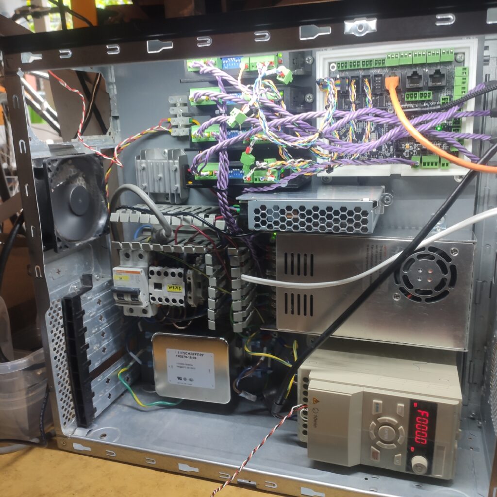
Electronics
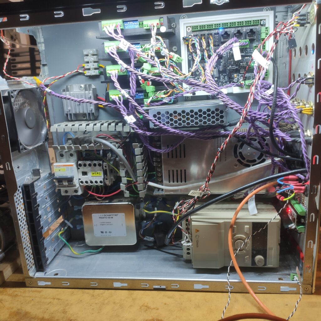
The primary components are as follows:
- FlexiHal 5-axis capable controller + Jog2K Keypad Pendant.
- 2x 2.4Nm NEMA23 Stepper Motors + 2x DM542T 4.5A Stepper Drivers (Y-Axis).
- 1x 3Nm NEMA23 Stepper Motor + 1x DM556T 5.6A Stepper Driver (X-Axis).
- GDZ80F-2.2B4 Spindle (air cooled, ER20, 2.2kW) + EV51S20022BX0 EV51 Series VFD.
- 24V 100W PSU for controller and sensors, 36V 350W PSU for steppers.
- Mains circuit breaker, contactor, line filter for VFD.
- 4-Core 18AWG unshielded stepper cable (X, Y axes).
- 4-Core 18AWG shielded cable (Z-axis, spindle).
- 4x LJ8A3-2-z/AX hall effect endstop sensors.


Painting and Reassembly
After the extended effort of moving the machine to it’s new home (the table doesn’t fit through regular doors, whoops!), the opportunity was taken to get everything painted while it was in a dismantled state. All the steel members were sanded and then de-greased using sugar soap followed by acetone, before being primed, and given ~1.5 coats of enamel spray paint.
The four base members (shown below left) used recycled box section, which had existing paint to be removed, done using a coat of paint stripper followed by hand scraping and sanding. The smaller components (motor mounts, brackets, rollers, z-axis parts) were pickled in an Oxalic Acid bath for around 24 hours to strip the mill scale before painting, though this approach proved unreliable perhaps due to an insufficient acid concentration, or buildup of surface debris preventing fresh acid from reaching the metal surface.


One Comment
Comments are closed.