
This post is an brief look into some novel part-cooling options for FDM printing, beyond the blown air typically used. This has largely been prompted by Jan of Roetz4.0’s Minuteman video series, where he is attempting to print a standardised “Benchy” part in under 60 seconds. This is at the extreme end of the so called Speedboat Race within the 3D Printing community, with the goal of printing a Benchy in the shortest time.
Recently he has been exploring some alternate coolants, notably compressed air, dry ice-chilled compressed air, misted Propanol, and compressed helium gas..
The problem of part cooling in FDM printing is simple in concept: the bead of molten plastic laid down by the hotend must be cooled to a solid before the subsequent layer, else the viscous and gravity forces will deform and sag the print to dis-satisfactory results.
In practice however, proper cooling design turns out to be one of the most important requirements for high speed printing. One of the most interesting takeways from Jan’s experiments has been that with a sufficiently responsive motion system and extruder, the only real obstacle to printing at sub one-minute speeds is infact just the part cooling – that is, the required extremely high extrusion rate from the nozzle, and rapid accelerations of the part, appear to not be a limiting factor.
Interjection! – WordPress seems to render hyphens as em-dashes so please don’t get the wrong idea. I promise I’m not AI 😉

Minuteman Benchy Print Parameters
The estimations in the post are based on Jan’s September 21st 2025 episode, in which he printed an 8.9g Benchy in 84s, a mass deposition rate of 105.95mg/s, at an average of 0.49 seconds per layer. With a density of 1.24g/cc for Fiberlogy High Speed PLA, the average volumetric flow rate is 85.5mm3/s. In the video he states peak flows of 190mm3/s which is inline with this number.
Extrapolating down to a one minute Benchy, the flow rate increases to 119.7mm3/s. For reference, the common Bambu Labs High Flow Nozzle can achieve only 65mm/s, just over half this value. Jan has gotten around this by a unique SLM printed hotend, with four spools of filament combined into a single nozzle. The intention of this is presumably to increase dwell time within the hotend, given the limited thermal conductivity of the plastic, and thus rate at which heat can be conducted into it. While the same effect could be achieved using an enlarged or split melt chamber in the manner of the CHT style nozzles, one can speculate that perhaps multiple filaments maintains a greater level of pressure control to prevent stringing.
A reference point – at 120mm3/s, a single filament extruder would require a filament feedrate of 49.91mm/s, with an extrusion rate of 954.65mm/s from a 0.4mm nozzle.
| Parameter | Value |
| Speed | 30k mm/s |
| Acceleration | 1750k mm2/s |
| Print Time | 84s |
| No. Layers | 192 |
| Design Mass | 89.74g |
| Measured Weight | 8.9g |
Thermal Requirements
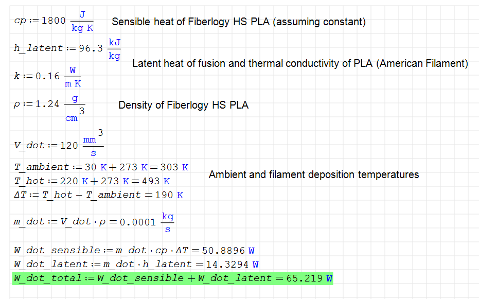
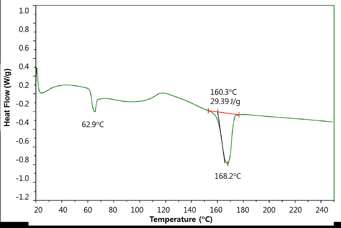
With 220C deposition and 30C ambient temperatures, the sensible heat of the filament dominates the required heat input, making up 78% of the 65.22W total. PLA being an amorphous polymer doesn’t have a defined melting point, though from the representative DSC graph below there appears to be a significant heat input at around 160C. Due to this we can expect a somewhat non-linear temperature profile of the molten filament as it cools and recrystallizes.
Coolant Properties
Before we can start meaningfully comparing coolant fluids, we need to at least define what metric we’re normalizing against!
There isn’t a singular obvious solution here, but one useful metric might be the reaction force applied to the print as the jet impinges on it. Excessive pressure on hot plastic could plausibly result in deformation of the layer, or ‘punching through’ of bridge sections such as the Benchy’s roof. Such force is a function of the momentum change of the fluid, and thus only its mass rate and velocity (assuming a constant deflection angle between coolants).
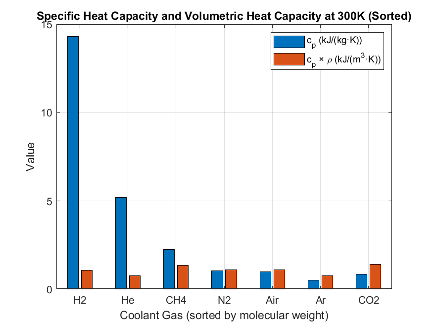
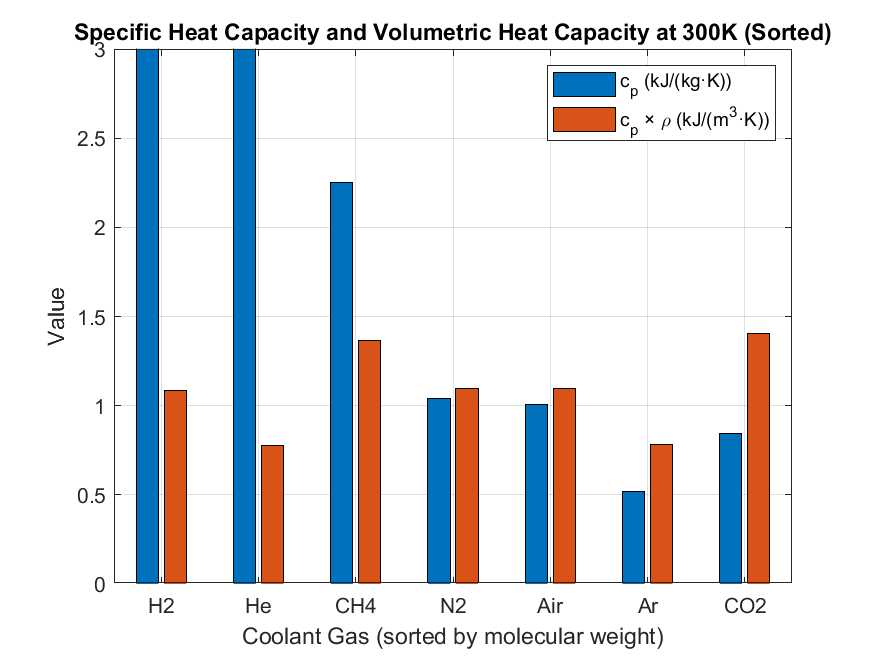
This presents us with two variables to optimize by means of fluid choice, namely mass rate and velocity. An easy starting point would be to choose a fluid with the highest specific heat (cp), and thus the lowest mass rate for a given flow velocity to maintain heat capacity. For most fluids however, this comes at the expense of fluid density and in turn a higher flow velocity for the same mass rate. The optimal solution must then be minimal product of specific heat and density (volumetric heat capacity).
Somewhat counterintuitively, it turns out that when considering the volumetric heat capacity and a constant reaction force, the light molecules traditionally considered as ideal coolants infact perform somewhat worse than regular air. The best performers of those examined were CH4 and CO2, possibly explained by the high hydrogen content of the former, and overall high density of the latter despite its relatively high atomic number makeup and correspondingly poor specific heat.
Pumping Power
Let’s have a look at pumping power. This is more relevant for blower-based cooling where we’re unlikely to see high local pressures applied to the part, and excessive pressure drops can be detrimental to blower efficiency and so are undesirable.
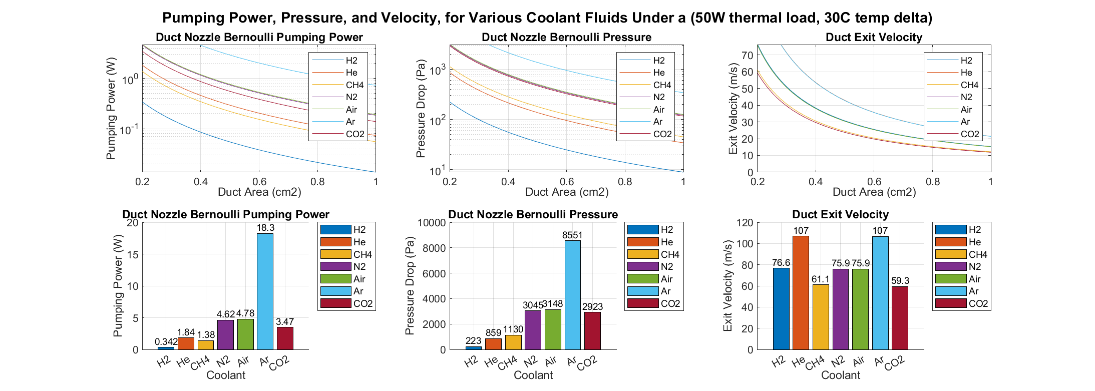
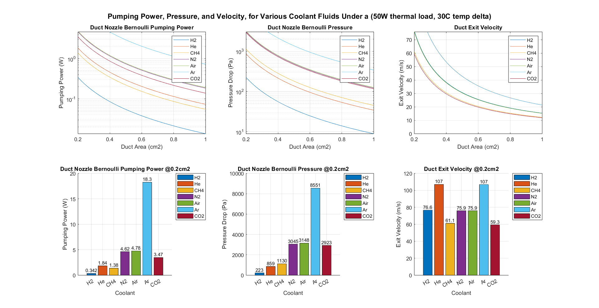
We can reasonably assume all our gasses are incompressible given the relatively low flow velocities (v<mach 0.3). For now let’s ignore pressure losses in the duct for simplicity. We will assume as heat load of 50W, equivalent to a 90s Benchy, and a duct nozzle opening ranging from 0.2cm2 to 1cm2. The coolant is assumed to be heated by a constant 30C. The required flow rate will be the heat load divided by the volumetric heat capacity. The exit velocity is then the flow rate divided by the opening area. Pressure drop and then pumping power can then be derived using the Bernoulli Equation.
It immediately becomes apparent that pressure drop heavily favors the lighter gasses, with hydrogen requiring only 0.223kPa at 0.2cm2, helium 0.859kPa, CH4 1.129kPa, and air, N2, and CO2 around 3kPa. Hydrogen also leads by a large margin in pumping power with 0.34W at 0.2cm2. The relatively heavy CH4 takes second place over helium however, due to the lower volumetric flow rate required despite a greater pressure head.
Heat Transfer
So far we have only compared coolants assuming a constant heat transfer coefficient. The velocity of the gas over the small size of the print means however that the time available for heat transfer is extremely short. For example, even at a relatively slow speed of 10m/s, gas will leave a 2cm diameter zone in only 1ms!
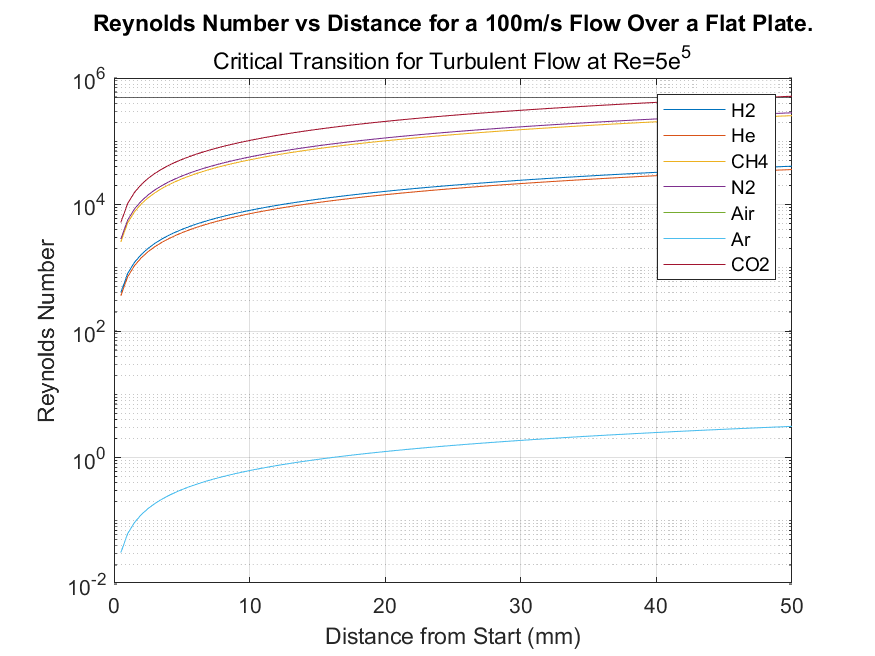
Parallel Flow Over a Flat Plate
Suppose we represent our coolant flow using the simple and often used parallel flow over a flat plate.
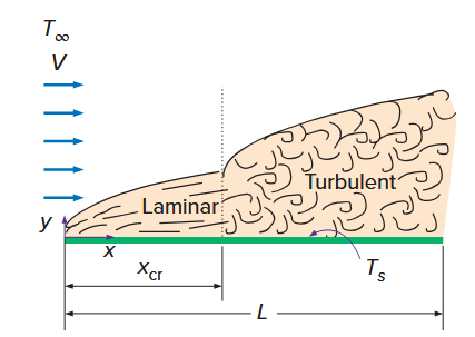
For this case, transition from laminar to turbulent flow occurs at a Reynolds Number of around 5e^5. Even at a flow velocity of 100m/s, nitrogen (air has been omitted from the below Re-plot) has achieved a Re half that of the critical value. Things are even worse for H2 and He, with values only around 40,000. The flat-plate case is a likely highly unrepresentative of the actual flow occuring, and one would expect the impinging flow from the duct onto part would induce turbulence from first contact. It is something to keep in mind however, particularly with the lighter gasses if flow velocity is not increased to compensate.
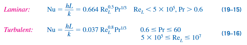
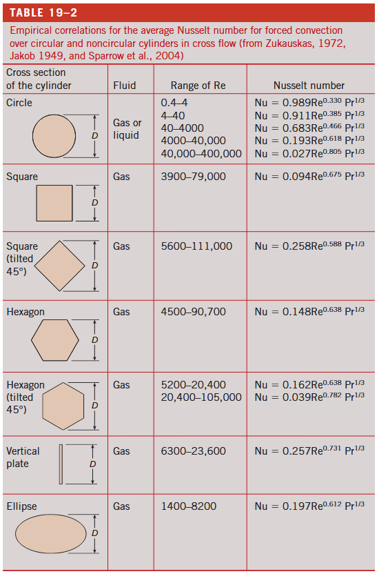
To find average heat transfer coefficient (h), we use correlations for the Nussult Number, which is a function of the Reynolds and Prandtl Numbers. The former as we have seen is tied to our gas choice and flow velocity, but the latter is always around 0.7 for the gasses being compared.
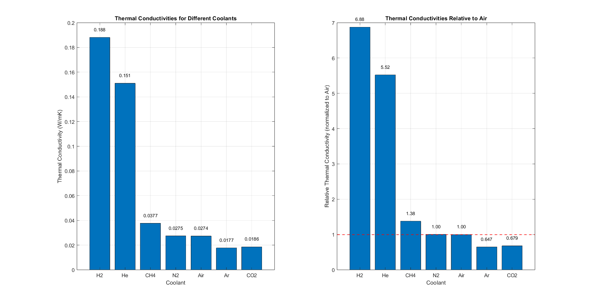
Besides the Nussult Number, the other relevant property is thermal conductivity (k), to which h is inversely proportional. This is good news for the light gasses, with hydrogen being almost seven times that of air, and helium 5.5 times, however unfortunately with the dependency on density by way of the Reynolds number, the effect on h is effectively cancelled out.
Takeaways
- To print a 9g PLA Benchy in 60 seconds, a heat input of around 65W is required, the majority of which goes to the sensible heat of the filament.
- Use of light-gas coolants such as hydrogen and helium have no advantage in cooling power for a given reaction pressure applied to the part by the jet of gas when compared to air. Methane and CO2 coolants perform slightly better than air under this criterion, due to their combined high densities and moderate specific heats, allowing lower flow velocities.
- The effect of hydrogen and helium’s high thermal conductivities is negated by their lower Reynolds Numbers compared to air, when considering the heat transfer coefficient and Nussult Number.
- The light gasses have a major advantage in pumping power and pressure, with hydrogen requiring 14x less power to accelerate the equivalent thermal capacity of air out of a nozzle compared to air, and helium 2.6x. Counterintuitively, methane performs better than helium under this criterion, requiring only 75% its power.
It should be noted that this is a crude analysis, and more thorough analytical calculations, as well as CFD simulations, should be performed for better certainty in the results.
PS – if anyone notices anything wrong in my calculations, feel free to contact me at benbridger2357@gmail.com
Appendices/Notes
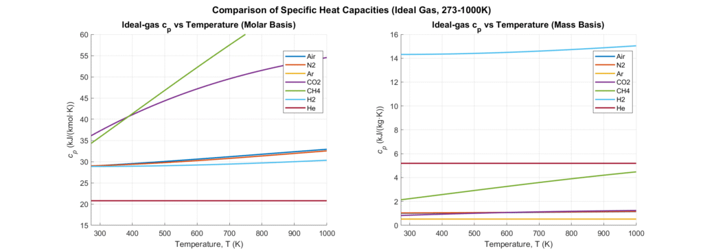
Note on specific heat with respect to temperature – For ideal gas relations >273K there is very minimal dependency on temperature, with the exception of CH4 and CO2 of the gasses considered. For our <~100C temperature deltas we can reasonably consider fixed specific heats.
https://www.engineeringtoolbox.com/gases-absolute-dynamic-viscosity-d_1888.html
https://www.seas3d.com/MaterialTDS-PLA.pdf
Correlations and most fluid properties taken from Cengel’s Fundamentals of Thermal Fluid Sciences
